Technical information
Overhaul of Mkviii engine
Meshing the bottom bevels
The vertical bevel should be inspected for wear or damage to the teeth, play in the bush and end-float. It is worth noting that the Mkviii engine had coarse bottom bevels when new but it is possible that they have been replaced by fine bevels during the intervening years. The coarse bevels are stronger and while fine gears will be strong enough for 'parading' it would be better to replace them with the gears that were originally intended to be used.
The bevel gear can be removed from the housing by resting the flange on open protected vice jaws with the gear downwards. The bevel can be driven through the retaining ring by tapping lightly using a brass or aluminium drift to avoid damaging the gear.
Reassemble by oiling the bush and inserting the gear into the bevel housing. Rest the gear teeth on a wooden bench and drive the retaining ring into place using a suitable piece of tube. The gear should be free to turn in the housing with no perceptible end-float.
Fit the crankshaft bevel gear in place using any shims that were present during dismantling. The keyway slot in the gear is engaged with the key on the mainshaft and the gear driven fully home. The gear is a light interference fit on the shaft and can be removed if necessary by light leverage.
The aim is to get the bevels meshing for the full width of the teeth with minimum backlash but no tightness at any point in a revolution.
It is quite difficult to get a good view of the enmeshment and a 'slave' bevel housing with a 90deg cutaway section and a gap of approximately 5/8" at the inside diameter of the bush is a real aid. See photograph A.
For initial meshing, remove the vertical bevel gear from its housing and insert into the slave housing. It is not necessary to fit the retaining ring or to consider gaskets and shims as we are only looking at how the horizontal bevel mates with the vertical.
Place the slave housing in place onto the lower bevel box with the cutaway to the rear and gently tap into place. It should not be necessary to use the 1\4" nuts, as the spigot will hold the housing in place. The relationship of the two gears will be quite easy to see by looking into the cutaway. When the gears are in full mesh, the angled faces form a single 'flat'. See photograph B.
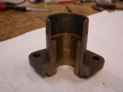
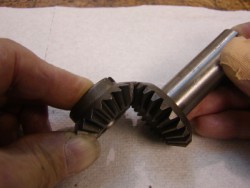
Photograph A - Slave bevel housing Photograph B - alignment of faces
With the vertical bevel free to move up and down, it can be determined whether the mainshaft bevel needs to go in or out. If outwards, shims can be added, if inwards, shims can be removed. It may even be necessary that material be surface ground from the back of the horizontal bevel gear, though this is unusual. Note : while it is possible that there could be a difference between the slave housing and the one that will be used, it will be minute and not enough to affect the final settings. The job can be done perfectly adequately without a slave housing but I find it to be useful.
Once the correct position of the horizontal bevel has been established, the vertical bevel gear is fitted back into its original housing.
Re-fit the bevel housing, using a paper gasket, into the bottom bevel box. Tap lightly in place and fit the 1/4" BSF nuts and washers but do not tighten at this stage.
Rotate the flywheels and gradually tighten the 1/4" nuts. If the flywheels became stiff to rotate, clearance will be required.
Should the flywheels be free to rotate when the housing is tightened down but there is backlash present, the clearance will have to be reduced.
Achieving final meshing of the gears requires patience and some skill. As a general principle it is better to err on the side of a small amount of backlash than to be tight in mesh. Having said that, the clearance will grow as the engine gets hot.
A further general principle is to use the minimum number of gaskets under the bevel housing. When new, the bushes had additional material on their thrust faces to allow the fitter to machine them very close to finished clearance on the gears, the rest being made up by one thin paper gasket.
If the clearance between the gears needs to be reduced, material can be removed from the steel flange of the bevel housing. Should the clearance need to be increased, material can be removed from the thrust face of the bush. This can be tricky to do and small amounts removed have a marked effect upon the clearance. So much so that it is easy to 'overdo' it and have to remove material from the other face. The safe way to do this is to turn a mandrel in the lathe onto which the bore of the bevel housing bush will be a push fit by hand. Squareness and concentricity is now guaranteed and the housing can be presented and re-presented quite easily. Clearance for a paper gasket must be allowed for when reaching a final fit.
Before final assembly of the lower bevel housing, it is well to check the flatness of the mating face of the bottom bevel box. It is not unknown for excessive tightening of the 1/4" nuts to pull the studs (and the surrounding area of crankcase) upwards. If this is the case, remove the studs and draw file the face flat, otherwise the bevel housing will not be sitting on a stable base.
Meticulous care is required at the final stages of assembly. The bevel housing is pulled down onto its studs and each gear tooth checked for backlash or tightness. It will invariably be found that even with an accurately aligned flywheel assembly, the clearance will not be not be the same during the whole rotation. There will be a tight spot and it is necessary to determine that there is some small perceptible movement at this point, clearances on the opposite side of the gear and elsewhere will have to be what they will be.. It is better to err on the side of a liitle more clearance than too little. We are talking about very fine measurements.
When the optimum clearances have been achieved, rotate the flywheel assembly briskly, using the connecting rod and listen to the gears, there should be no harsh noises given off and the mesh should feel 'silky', with no suggestion of tightness. Add a little oil to confirm that things do not change.
When the optimum meshing has been achieved, brush a thin coat of 'Wellseal' onto the two mating faces, fit a thin paper gasket and tighten the nuts. Be aware that even at this late stage, it is possible for the Wellseal to soften the gasket and allow a further unwelcome reduction in the clearance.
Rob Drury November 2006
Thanks to Peter Miles for proof reading and offering some corrections and clarifications.